Cosmic ray muons are produced in the upper atmosphere and reach the earth. They are heavier than electrons but elementary. They have a finite lifetime of 2.2 microseconds and travel at close to the speed of light. They are not only elementary particles that attract the interest of physicist at large particle accelerators including the compact muon solenoid (CMS) experiment at CERN, but have recently been explore for climate studies and archaeology as well.
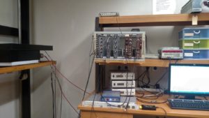
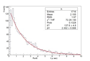
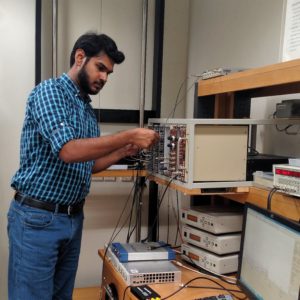
In the Physlab, our advanced lab students conduct an experiment which measures the lifetimes of muons using plastic scintillators and photomultiplier tubes (PMTs). These lifetime measurements have been improved by incoming undergraduate student from the Habib University, Muzammil Abbasi. A presentation describing his work can be viewed here. Here is a video log of his work too.
Recently, we have made several original contributions to the tools that are necessary for compact, accurate and innovative measurements of muon’s properties. For example, this webpage describes details of a simulator for muon tracking and scintillation modeling as well as an FPGA implementation of a time-to-digital converter (TDC).
In fact, the implementation was started by a visiting student from NUST’s EME, Sultan Abdul Wadood who is now pursuing his PhD at the University of Rochester. He completed his final year project in our lab and produced this thesis. Details of our FPGA implementation are under review with the Review of Scientific Instruments and the manuscript will be shared here soon.
Going further down the memory lane, Uzair Abdul Latif, made the first attempt of measuring muon speeds with fractionating discriminators and nuclear instrument modules. His work can be seen here.
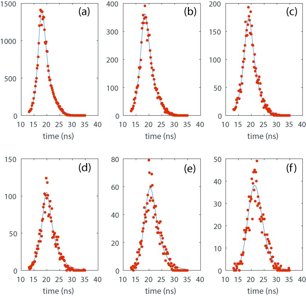
Histograms of time-of-flight measurements fitted to an asymmetric Laplace distribution convolved with Guassian noise is shown below.
Table of Contents
PhysLab Muon Simulator
This software tracks the trajectories of muons in air and as they pass through a pair of scintillators. These scintillators flash with photons and the photons trigger electronic signals in photomultiplier tubes. The software allows to extract timing information of these events. Here we describe the installation and usage of the software.
Requirements
- PhysLab Muon Simulator (https://bit.ly/physlab_muon_sim)
- Matlab R2015b or later
- Microsoft .Net Framework 4.5.2 (https://bit.ly/dotnet_4_5_2)
Introduction
The PhysLab Muon Simulator can be used to simulate a shower of cosmic ray muons on a set of rectangular scintillators for analyzing their transmission speed and some other important aspect of the process. The simulator provides a graphical user interface written in Microsoft Visual C Sharp for a partly Matlab based algorithm.
Using the Program
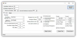
Make sure that the computer has a working installation of Matlab 2015b and .Net Framework 4.5.2. Download the simulator from https://bit.ly/physlab_muon_sim, extract and run the main executable named “MuonSimulation.exe” placed under “MuonSimulation\MuonSimulation\bin\Debug”. Most elements of the GUI are programmed with self-popping tooltips which means that hovering the mouse cursor over them for more than half a second will show a balloon tip about the usage of the respective element. With the help of the self-popping tip balloons, most of the simulation becomes self-explanatory. Some of the significance and usage of some important elements shown in Figure 1 will now be explained.
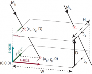
The top section first generates the specified number of Muons on a scintillator of specified dimensions. The simulation assumes a configuration of the scintillators defined in Figure 2.
An illustration of the geometric configuration assumed by the simulator for calculating the transmission speed. Two scintillators of dimensions WxH placed parallel to the horizontal plane right above each other at a distance of DA. Each scintillator is equipped with a PMT placed at (W, H/2, 0) and (W, H/2, D) respectively with reference to the shown Cartesian coordinate system. A muon MN is shown to be striking the upper scintillator at a point (XA, YA, D) and the lower scintillator at (XB, YB, 0) after passing through the upper scintillator. The photons generated by the interaction of the muon and the scintillators will travel straight paths to the respective PMT tubes in order to get detected.
The simulation can be run for any number of scintillator spacings and any number of transmission speed specified in the “Parameters” group of the “TDC output” section. These values can be entered into comma-separated ranges. Some valid examples are:
| Values produced | Code |
| A single value of 10 | 10 |
| 11 values 10,11,12…20 | 10:20 |
| 6 values, 10,60,110,160,210,260 | 10:50:200 |
| 11 values, 10,11,12…20 | 10-20 |
| Produce Values: 1, 3, 10, 11, 12…20, 100, 400, 700, 800 | 1,3, 10-20,100:300:750, 800 |
Some other values that the simulator allows to customize will now be listed:
| Item Name | Significance |
| SD of simulated Gaussian error | The simulator can assume the measuring TDC to have a Gaussian noise in the input channels. To mimic an actual TDC, this error can be measured first on an actual TDC and then entered into the simulator. |
| Scintillator height spacing | This offset will be added to all the heights entered in the scintillator spacing entry box.
This means that an offset of 20 with scintillator spacing of 1:10 will actually run the simulation for values: 20, 21, 22, 30 |
| TDC Offset | To compensate for the phase difference in different input lines of the TDC this parameter can be given some non-zero value. |
| Azimuth distribution resolution | This number should be, at most, half of the number of muons.
It represents the number of bins assumed in the cosine square distribution used for assuming the muon inclinations. Any value between 150 and 2000 should work just fine. |
Associated with every combination of speed, spacing, and selected test, some shareable Matlab variables are produced which can be further investigated in Matlab. These variables can be viewed and exported in the “Matlab” section of the simulator. Since the same process is run multiple times with different starting parameters, the application uses a systematic way for the naming of these variables. Each test result variable name is defined as a format that includes programmable keys that guide the simulator what symbols to use in replacement. For example, each run of speed test produces three quantities, named ToF, histcenters and bincounts. The specified naming format can contain keys {Q}, {d}, and {v} which will be replaced by the name of the quantity, spacing, and assumed speed, respectively. The usage can be more clearly understood by simply running the simulator with some preset parameters.
Speed Test
The simulator provides multiple tests, the most significant of which is the speed test. This test is designed to simulate the time of flight of muons between multiple scintillator spacing and multiple assumed transmission speeds. To run this test,
- Specify the dimensions of the scintillators,
- specify and generate some muons to be simulated; a muon count of 8000 will produce mildly course results,
- enter a range of scintillator spacings, say 19:20:120 cm,
- enter an assumed transmission speed and TDC input error
- and run the speed test.
The simulator can also be told to save the histograms of the TDC results which will produce variables with names according to the defend naming format.
To change the number of muons in the simulation, the simulator must be restarted.
Time Division Test
This test is defined to investigate the distribution of the three components of TDC time measurement TA, TB, TF as we describe in the analysis. Along with producing the Matlab variables, the simulator also plots the distributions of these components on separate plots.
Deployment of the TDC code on the FPGA
We have also implemented a time-do-digital converter (TDC) on an FPGA board. The code allows to measure speeds, fluxes and lifetimes.
Requirements
- TDC source code (https://bit.ly/fpga_tdc_source_code)
- Digilent Genesys Board (https://bit.ly/digilent_genesys)
- Xilinx ISE Suite (https://bit.ly/xilinx_ise)
- Digilent Adept (https://bit.ly/digilent_adept)
- A working USB port
The software required for the deployment of the TDC are free of cost but some import conditions may apply for the download.
Modifying and configuring FPGA
The source code contains a pre-compiled .bit file that can be used to directly configure a Digilent Genesys board, however, if one needs to modify certain aspects of the design, or an FPGA other than Xilinx Virtex-5 LX50T, the following steps would be needed. Please note that once configured, the FPGA retains the configuration in its flash and will be ready to work after power reset without needing to be re-configured.
- Xilinx ISE is required to create the data required to configure the FPGA according to the HDL source code. Download Xilinx ISE suite from the Xilinx official website and install it.
- To use the FPGA source code, open “main.prj” from the extracted source code directory in to Xilinx ISE.
- The code is structured in various files, the most important verilog HDL files of which are listed below. These files contains comments around various significant portions of the code.
- The top level module is defined in Main.v which instantiates essential TDC modules and links them together,
- v implements the main TDC. It instantiates the TDC signal multiplexers, TDLs and implements a state machine that is responsible for clock counting and TDL snapshot registration,
- v instantiates a UART bus and some registers shared by other modules of the TDC. This module is responsible for pulling time data out of the TDC and pushing it into the UART buffer in form of a checksum protected data packet,
- v provides a way to create a delay line with an optional implementation of taps using NOT gate pairs in the FPGA,
- v implements a fixed period pulse generator the duty of which can be accessed by the DataLink and
- v and UART.v respectively implement a simple UART for data transmission and a cyclic buffer on top of it.
- The FPGA required a *.bit file for configuration which can be compiled by running the process “Generate Programming File” in the processes pane for the main module. Once all the chained processes are finished successfully, a “bit” can be accessed in the main project directory along with all the other files. See figure 1 which shows screenshots of these steps.
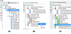
Figure 1: (a) shows the implementation view of the TDC project. (b) shows an incomplete process window for the main module. (c) shows a view of the process window after the generation of the .bit file.
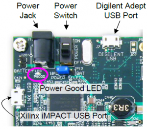
- Power up the genesis board using the supplied power adapter. Connect the Digilent Adept USB port of the Genesys board to the computer and open Digilent Adept. If Digilent Adept is properly installed, the computer automatically installs the required USB drivers upon connecting the Genesys board. This can be confirmed if “Genesys” is enlisted in the top right corner of the software.
-
- Browse to the “Flash“ tab of Digilent Adept and choose the created “bit” file as the programming file and “BPI” mode of the Flash to “Up”. This must be followed by StrataFlash jumper of the Genesys board set to “BPI Up”.
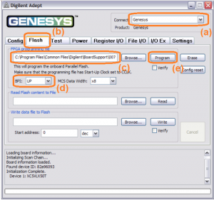
Figure 3: A screenshot of Digilent Adept connected to a Genesys board. (a) is the name of the connected board (if any). (b) shows that the “Flash” tab is selected. (c) is the section containing the name of the programming .bit file. (d) set the BPI setting to be used and (e) initiates the programming process once everything else is setup.
- Browse to the “Flash“ tab of Digilent Adept and choose the created “bit” file as the programming file and “BPI” mode of the Flash to “Up”. This must be followed by StrataFlash jumper of the Genesys board set to “BPI Up”.
- Program the FPGA. This will take some time but as soon as the process finishes, toggle the power switch of the Genesys board once for the configuration to take effect. The FPGA is now configured and running the TDC code.
Data Connection
To physically connect the TDC with the computer for communication, a serial-USB bridge is needed. This can be accomplished using either of the following devices:
- FTDI USB-serial module e.g. https://bit.ly/ftdi_amazon
- CH340 USB-serial module e.g. https://bit.ly/ch340_sparkfun
- An Arduino running “Serial Passthrough” example (https://bit.ly/serial_passthrough). Note that the Arduino needs to be running at 3.3V or a voltage shifting scheme must be used to provide the data to the FPGA at 3.3V (e.g. https://bit.ly/3v3_5v). Any current source at voltages higher than 3.3V can permanently damage the FPGA chip. Also, the code needs to use the same baud rate as the one used for the PC connection as we discuss later in this section.
Each USB-serial bridge provides a pair of Rx/Tx pins similar to the ones found on the FPGA. The Tx and Rx pins on the FPGA can be changed using the user configuration file, config01.ucf in the Xilinx ISE. By default, Rx is set to pin 10 on Genesys port J, and Tx to pin 2. To connect, the FPGA with the USB-serial bridge, the “Tx” pin of one end goes to the “Rx” pin of the other and the ground pins need to be connected. Once the USB drivers for the selected USB-serial bridge are installed and the connections are made, the TDC is ready to be connected to a computer utility that can communicate with the TDC.
Using the Matlab TDC Interface
Requirements
- Matlab R2015a (or later)
- Instrumentation Toolbox of Matlab
- A working USB-serial hardware connection of the PC and the configured FPGA
- TDC user interface (Download link: https://bit.ly/tdc_matlab)
Hardware setup
Once the FPGA is configured and connected using the USB-serial bridge to the PC, all of its functionalities can be accessed using the Matlab command-line interface for the TDC. To explain the usage of the TDC, we take an example of measurement of the lifetime of Muons using a setup explained in https://bit.ly/3fx58HI. The experiment requires the TDC to measure the time between two pulses. The first pulse is named AB, which is an AND output of two signals, A and B. B2 is a signal representing the decay of a Muon causing the signal AB. C may also be used as a veto to reduce false positives which would mean that any signal on C will abort the measurement process. However, in this example, no veto will be used.
All three signals, A, B, and C are first passed through a NIM discriminator which produces a NIM output of -1.6V. This output is passed through individual high speed inverting amplifiers to get an output of 3.3V compatible with the FPGA. These signals are now fed to the FPGA on any three pins of the user ports JA, JB, JC or JD on the Genesys board.
Software Setup
Browse to the TDC interface directory which contains SampleCode.m file containing the code for the example under discussion. Once an understanding of the actual experiment has been developed, the code can easily be understood with the help of in-line comments. Summarily, the code first initializes a DataLink object to communicate to the TDC. It then configures the TDC to behave in the way required for this experiment and initializes an automatic timed process to record the time measurements of the TDC.
