| Student Manual |  This innovative experiment entails the determination of the Curie point of a ferromagnetic alloy. An alternating current is passed through the alloy, (also used as a heating element in industrial furnaces). The alloy, at room temperature, is attracted towards a strong permanent magnet while the voltage, current and time are constantly monitored. As the alloy heats up, a point reaches where the alloy loses its magnetism and snaps away from the magnet. The Curie temperature is then determined from the current, voltage, time, surface area, length of the alloy and its emissivity. This experiment will be performed in the close supervision of the instructor, who will guide the students through the appropriate safety protocols. |
| Hardware Manual | Resistance Heating Alloys and Systems for Industrial Furnaces |
| Experiment Code | 1.4 |
| Version | 31 October 2013 |
Further Readings and References
- Hysteresis in Light Bulb: Connecting Electricity with Thermodynamics with simple experiments and simulationsEuropean Journal of Physics, D.A. Clauss, R.M. Ralich and R.D. Ramsier, 22, 385, (2001).
- Continuous Magnetization Patterns in Amorphous RibbonsIEEE Transactions on Magnetics, S. Rudolf, H. Giselhe, 37, 2245, (2001).
- Simple Experiment to Help Students Understanding Magnetic PhenomenaThe Physics Teacher, K. Browne, D.P. Jackson, 45, 425, (2007).
- Finding the Curie Temperature for Ferromagnetic MaterialsThe Physics Teacher, K. Czestaw, S. Budzik , and C. Jozef, 45, 31, (2007).
- Measurement of Curie Temperature for Gadolinium: A laboratory Experiment for StudentsEuropean Journal of Physics, T. Lewowski, K. Wozniak, 18, 453, (1997).
- Determining the Curie Temperature for Iron and NickelThe Physics Teacher, S. Velasco, F.L. Roman, 45, 387, (2007).
Pictorial Procedure
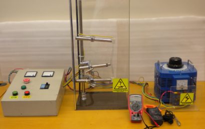
1. Provided apparatus
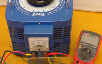
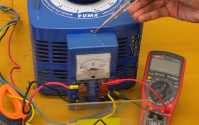
2. Connecting a digital volteter to the variac

3. Clamping a clamp meter to any one of the variac output lead

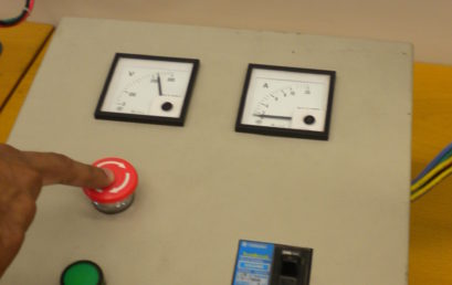
4. Set the variac at 0V, switch on the mains supply and press green START button
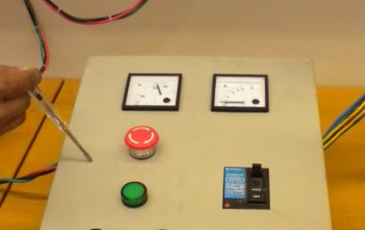
5. Checking for current leakage in the control box
6. Current leakage check in the pole
7. Current leakage test in the variac
8. Testing the emergency stop button
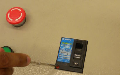
9. Circuit breaker check
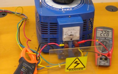
10. Set variac at 22V. The operating voltage range lies between 22-30V
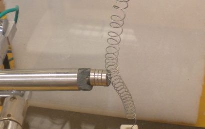
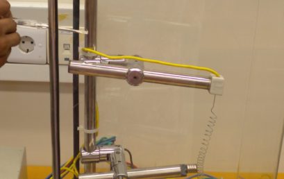
11. Kanthal wire attached to the magnet
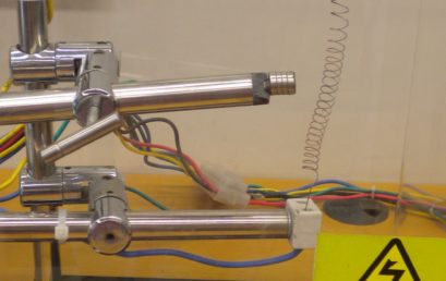
12. Kanthal wire snapped away