 In this experiment, PhysLogger together with its compatible sensing instruments (called PhysInstruments) will be used to verify ideal gas laws, that are the Amonton’s, Boyle’s, and Charle’s laws and investigate engine cycles. The experiment is a great depiction of thermodynamic cycles and actually generates the PV curve. |
|
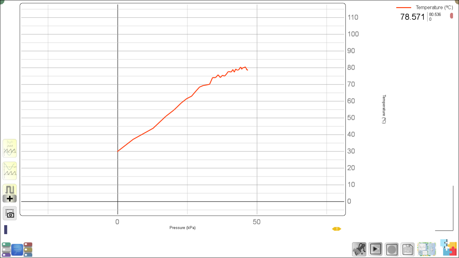
| Sample Results | Boyle’s LawCharle’s LawAmonton’s LawPV Cycle of a mass lifting Heat EngineAmonton’s LawCompiled data from a run in 2024 acquired by Wajahat Sami |
| Hardware Manual | V1 Application Note Heat Engine Experiment |
| Experiment Code | 1.17B |
| Version | 2022-v1 |
Further Readings and References
- Syringe thermodynamics: The many uses of a glass syringeAmerican Journal of Physics, David P. Jackson and Priscilla W. Laws, 74, 94, (2005).
Pictorial Procedure
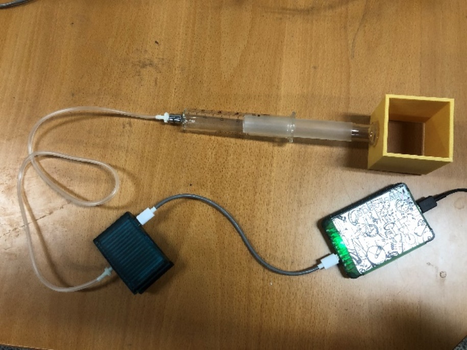
Boyle’s Law:
Boyle’s Law tells us that pressure P is inversely proportional to volume V when temperature T is kept constant, i.e., PV=constant. Connect the syringe through the Tygon/nylon tube to PhysBar. The PhysBar module is connected to a digital channel of PhysLogger. Connect the syringe through the nylon tube to PhysBar. In PhysLogger Desktop, go to Measure > Pressure. Observe how the pressure varies on the LivePlot of PhysLogger Desktop App as you increase and decrease the volume of the air inside the syringe by expanding and compressing the syringe.
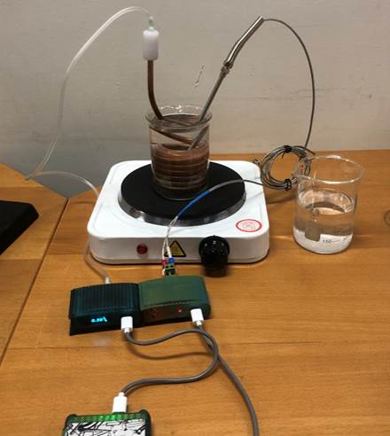
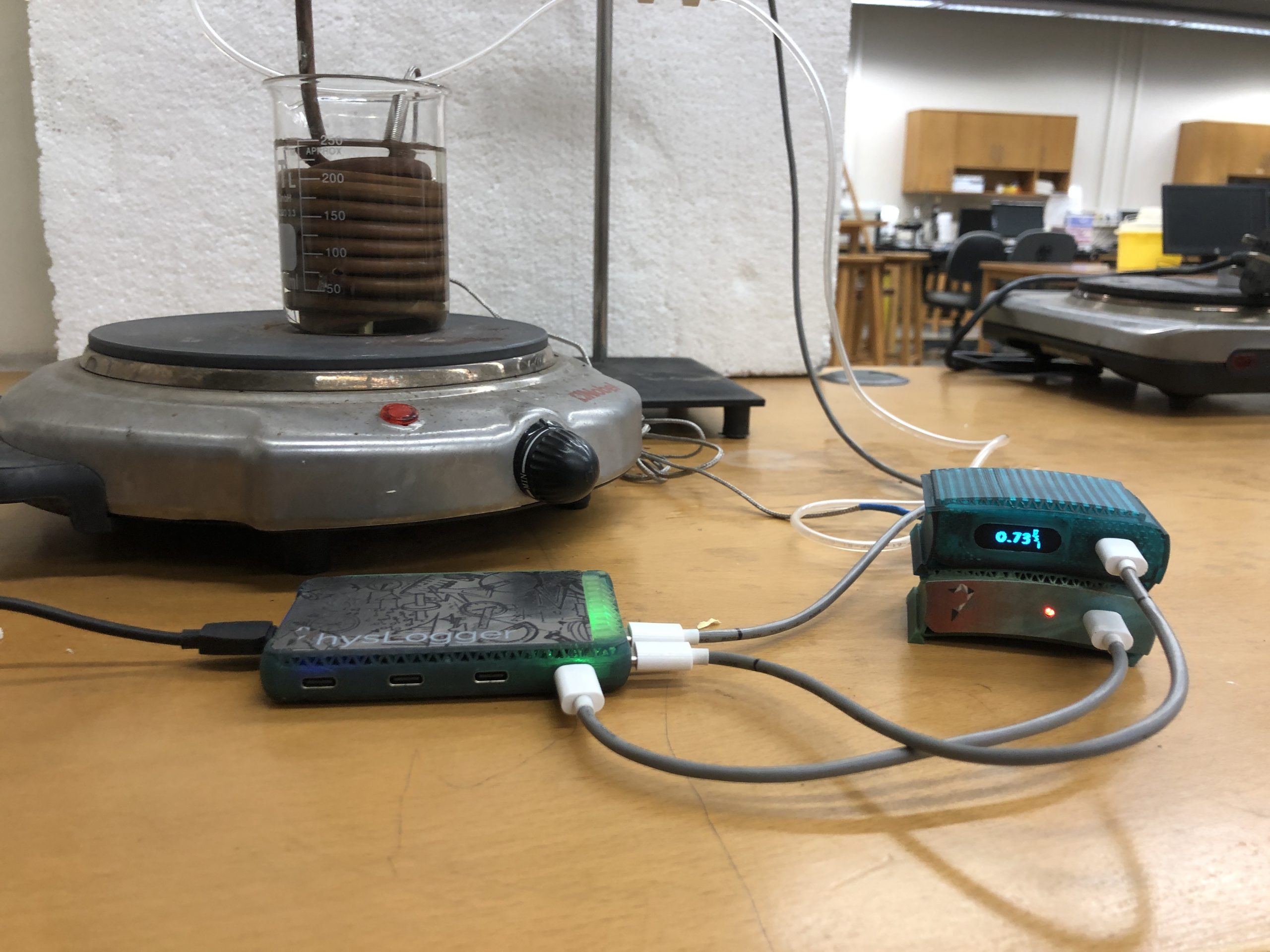
Amonton’s Law:
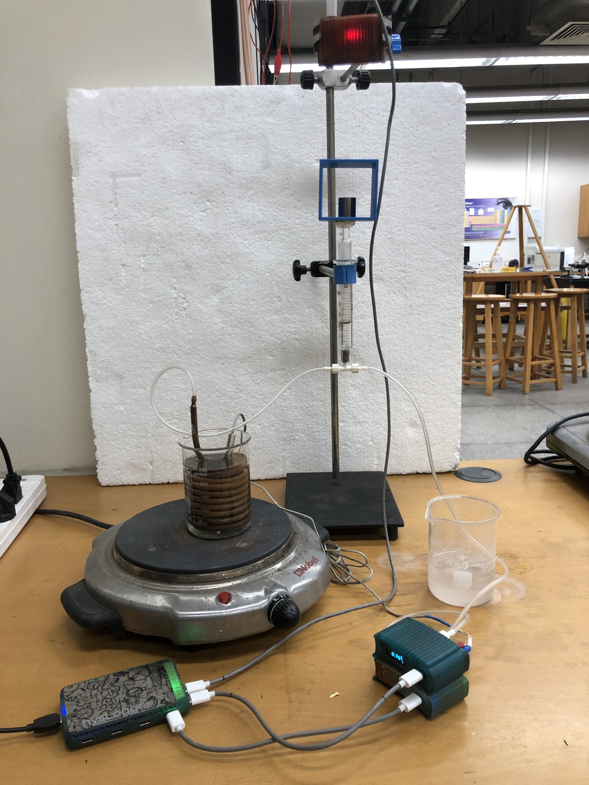
The copper coil is connected to Physbar. Physbar is connected to a digital channel Phsylogger in the usual way (refer to the section on Boyle’s law). The copper coil is immersed in about 150 mL of water inside a 250 mL beaker and placed on a hot plate. A probe thermocouple is introduced inside the coil. The Thermocouple is attached to PhysTherm and the amplified output from this module reaches one of the analog channels of PhysLogger.
Charles’s Law:
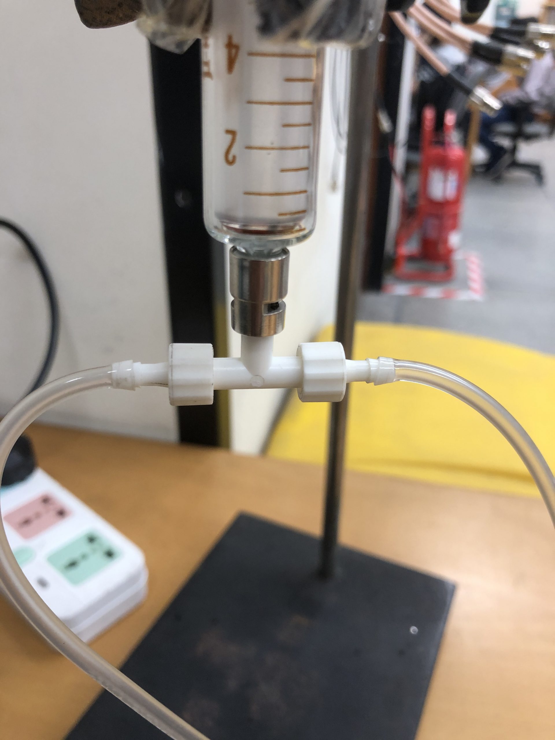
In this part of the experiment, the copper coil is connected to a flexible tubing with a plastic tee at the other end. The tee has three ports. One port goes to the copper coil. The second part is exposed to PhysBar. The third part is connected through another flexible tubing to the glass syringe. The electrical connections of the thermocouple and PhysBar to PhysLogger remain unchanged.