| Student Manual |  This innovative experiment gives you an introduction of blackbody radiation and Planck's radiation law. The experimental objective involves the determination of the numerical value of Planck's constant using incandescent light bulb as a source of blackbody. Students will also practice error propagation and learn how to measure important parameters using weighted fit of a straight line. |
| Software Code | MATLAB code for uncertainty calculation |
| Sample Results | Measuring the value of Planck’s ConstantFinding the value of Gamma |
| Experiment Code | 1.11 |
| Version | 5 January 2016, 2016-v1 |
Further Readings and References
- Temperature of incandescent lampsAmerican Jornal of Physics, Vittorio Zanetti, 53(6), 546, (1985).
- Basic Physics of the Incandescent Lamp (Lightbulb)The Physics Teacher, Maclsaac, Dan, Gary Kanner and Anderson Graydon, 37, 520, (1999).
- Standard A-shape clearPhilips/lighting, Koninklijke Philips Electronics N.V, .
- Calibration and temperature profile of a tungsten filament lampEuropean Jornal of Physics, Charles and Jean-Michel Gitton, 31, 933, (2010).
- Planck’s constant determination from black-body radiationAmerican Journal of Physics, Dryzek, J. and Ruebenbauer, 60(3), 251, (1992).
- Planck’s constant determination using a light bulbAmerican Journal of Physics, Brizuela, Graciela and Alfredo Juan, 64(6), 819, (1996).
- Blackbody radiation and Planck’s hypothesisPhysics for Scientists and Engineers with modern Physics, Raymond A. Serway, John W. Jewett, Jr, 1186, (2010).
- Planck’s radiation lawModern Physics, Thomson learning, Raymond A. Serway, Clement J. Moses, and Curt A. Moyer, 68, (2005).
- Thermal or blackbody radiationPhysics, John Willey & Sons, Inc, D. Halliday, R. Resnick and Kenneth S. Krane, 1021, (1992).
Pictorial Procedure
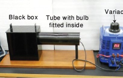
1. Provided apparatus |
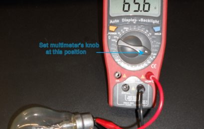 2. This is how you’ll measure the room temperature resistance of an incandescent light bulb 2. This is how you’ll measure the room temperature resistance of an incandescent light bulb |
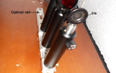 3. An assembly of optical components on the optical rail 3. An assembly of optical components on the optical rail |
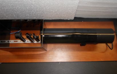 4. Place optical components inside the black box and insert cylindrical tube (having bulb fitted inside) into the black box 4. Place optical components inside the black box and insert cylindrical tube (having bulb fitted inside) into the black box |
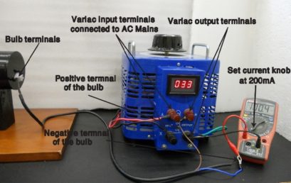 5. The incandescent light bulb is connected to the variac through an ammeter in series 5. The incandescent light bulb is connected to the variac through an ammeter in series |
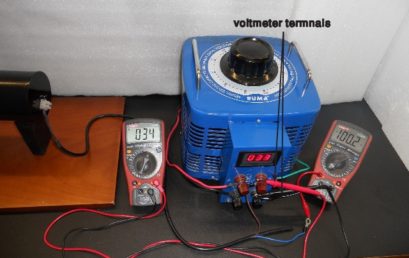 6. Circuitry of the setup. A voltmeter is connected in parallel configuration while an ammeter in series 6. Circuitry of the setup. A voltmeter is connected in parallel configuration while an ammeter in series |
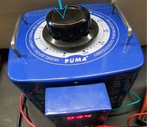 7. Rotate dial of the variac in clockwise direction to get variable voltages 7. Rotate dial of the variac in clockwise direction to get variable voltages |
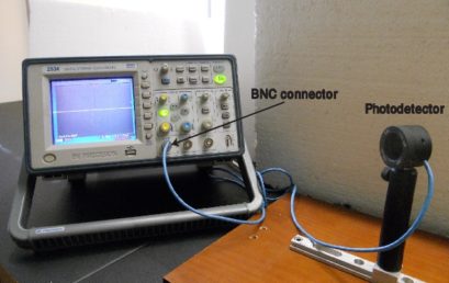 8. Connecting a photodetector to the digital oscilloscope 8. Connecting a photodetector to the digital oscilloscope |
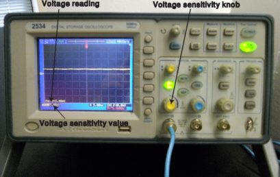 9. Adjusting voltage sensitivity range of a digital oscilloscope 9. Adjusting voltage sensitivity range of a digital oscilloscope |